Up to R-21 and a Radiant Reflector (Maximum Benefit Application)
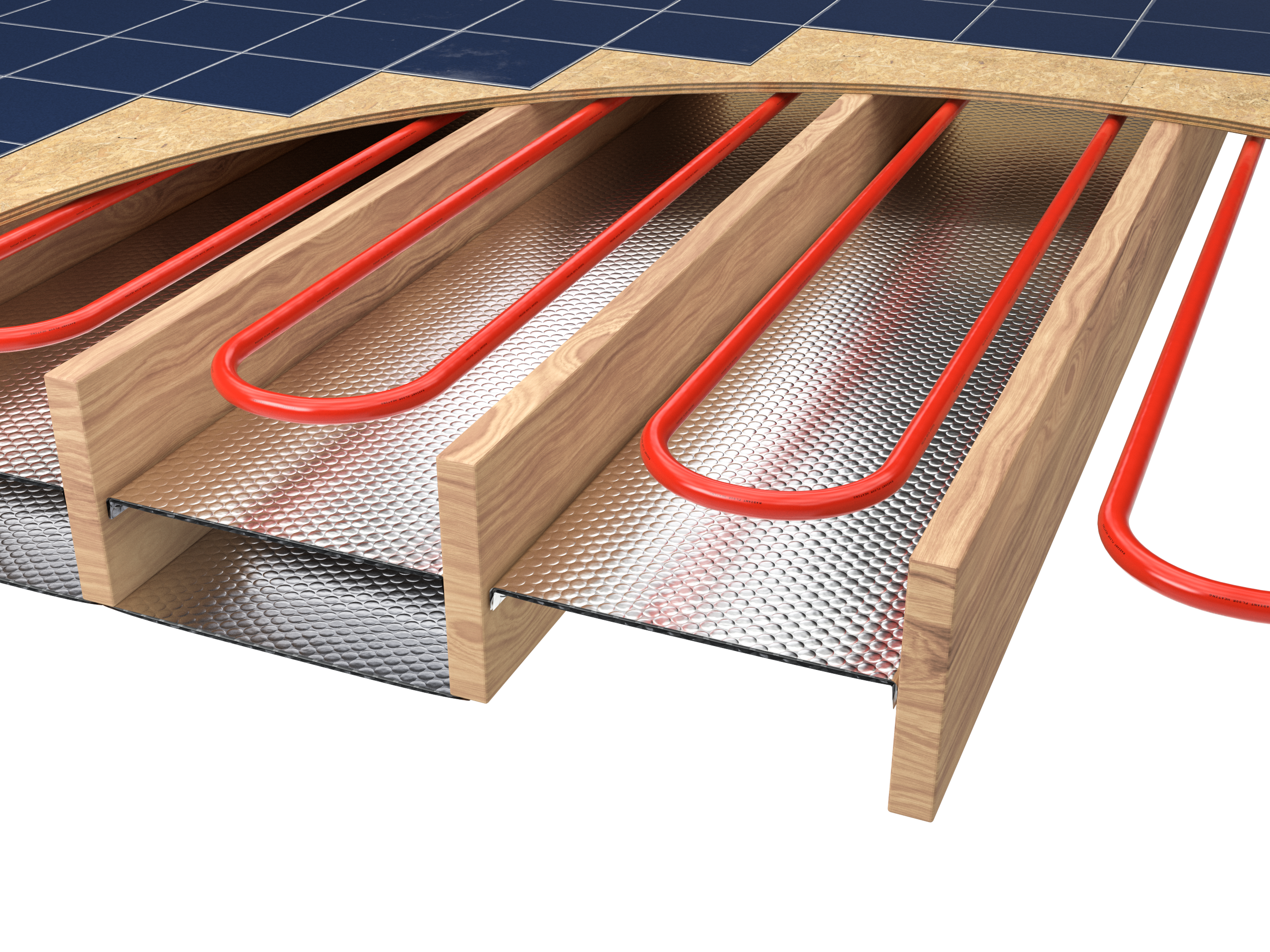 Note: Installation instructions and illustrated drawings are recommendations only, while proper local construction methods are the responsibility of the installer.
This application is ideal for a radiant floor system above or below a wooden (joist) sub-floor. The benefits provided by Reflectix® are dramatic. In addition to an impressive R-21, the reflective film provides a 96% reflectivity of radiant energy back into the system. The product has the added attraction of ease of handling and installation.
Product Description
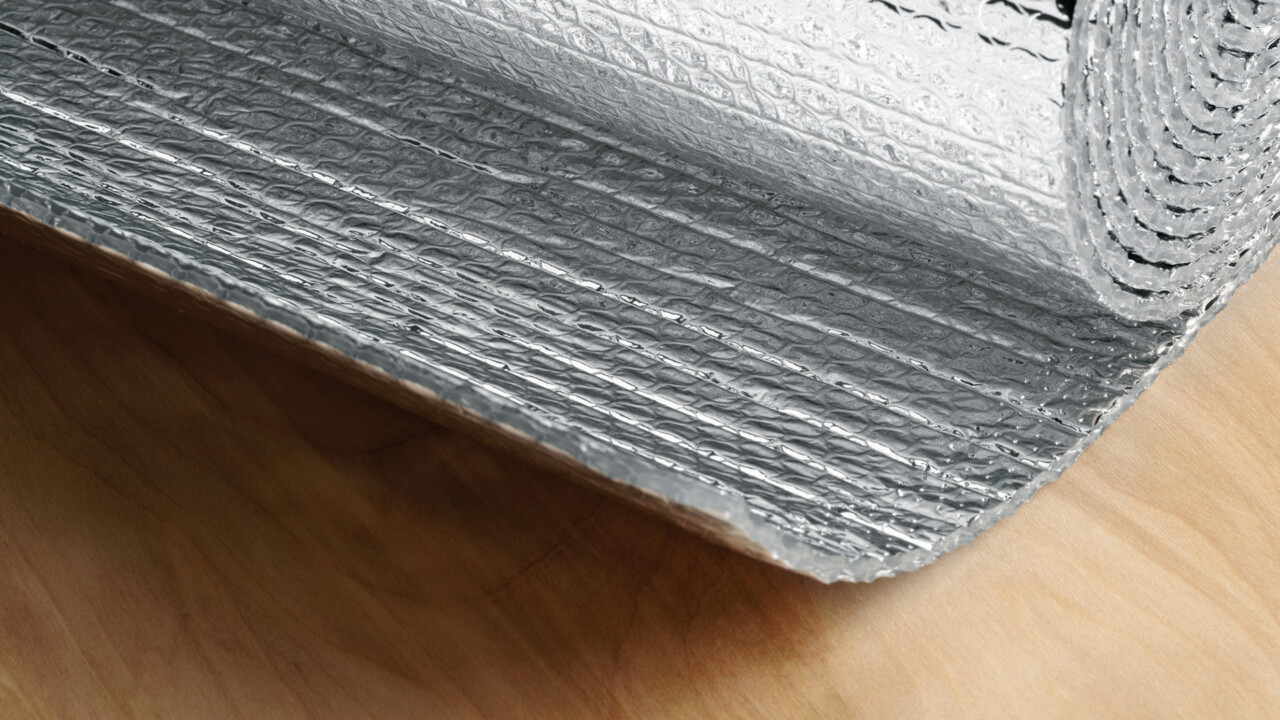
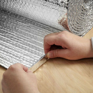
The Reflectix® Double Reflective Insulation consists of two layers of highly reflective film (96% reflectivity) that are bonded to two tough layers of polyethylene. Two inner layers of insulating bubbles and a center layer of polyethylene provide this easy to handle product with high strength and reliability.
Benefits
- Reduces installation labor because of its easy to handle and install characteristics
- Reflects 96% of radiant heat back up into the living space
- Reduces annual energy costs of the system
- Up to an R-21 and fiber-free
- Directs heat into living space
- Costs less to install
- Enhances even heat distribution across the floor surface
- Does not require protective clothing
- Resists growth of fungi, mold and mildew or respirators to install
- No nesting characteristics for insects
- Vapor and radon retarder
- Non-toxic / non-carcinogenic
- When properly installed, inhibits ground moisture from causing dry rot (installed to the bottom of the joists over a crawl)
- ISO 9001:2015 certified manufacturing location
Part Numbers and Sizes
- HVST16050 (16”x 50’)
- HVST16100 (16”x 100’)
- HVST16125 (16”x 125’)
- HVST48050 (48”x 50’)
- HVST48100 (48”x 100’)
- HVST48125 (48”x 125’)
Technical Data
- Temperature Range: -600 to 180 F
- Nominal Thickness: 5/16 inch (.312)
- Weight: 0.771 oz./sq. ft.
- Flame Spread Index (ASTM E 84): Less than 25
- Smoke Developed Index (ASTM E 84): Less than 50
- Fire Rating: Class A/Class 1
- Linear Shrinkage: None
- Reflectance (IR): 96%
- Water Vapor Transmission (ASTM E 96): 0.02
- Puncture Resistance: 60 lb./in.
- Mold and Mildew: No Growth
- Emittance: 0.04
- Tensile Strength: 3.7 N/mm
- Pliability: No Cracking
- Hot Surface Performance: Passed (250 F)
- Note: Not for use in direct contact on surface temperatures that are 1800 F or greater.
Testing and Certification
- Thermal Performance of Wall Systems ASTM C1363
- Thermal Performance of HVAC Duct System ASTM C335
- Thermal Performance of Crawl Space ASTM C1363
- Hot Surface Performance ASTM C411
- Heat Transfer (Heat Flow Up, Down, Horizontal) ASTM C1363
- Thermal Performance of Reflectix® and Fiberglass in Walls ASTM C1363
- Heat Transfer of Air-Handling Ducts with Reflectix®
- Flame Spread and Smoke Density ASTM E84
- Mounting Method ASTM E2599
- Fungus Resistance Mil-Std 810B Method 508
- Pliability Test ASTM C1224
- Sound Absorption Test ASTM C423 and ASTM E795
- Sound Transmission Loss ASTM E90 and ASTM E413
- Water Vapor Transmission ASTM E96
- Tensile Strength ASTM D751
- Emittance Testing ASTM C1371
- Thermal Performance of Water Heater Jackets
- Intertek: Surface Burning Characteristics of Building Materials ASTM E84 (Taped Joint Detail) Test Report # 3166908SAT-012
- Intertek: Surface Burning Characteristics of Building Materials ASTM E84 (Unslit) Test Report # 3166908SAT-011
- R&D Services: Resistance to the Growth of Fungi ASTM C1338 Test Report # RD072713FR
- State of California
- State of California Licensed Insulation Manufacturer
- State of Minnesota: Filed with Minnesota Insulation Standards Program
- State of Wisconsin: Wisconsin Material Approval, Safety and Buildings Division Approval # 920088-1
- R&D Services Emittance Testing
- R&D Services: Physical Properties Sheet Width, Length, Pliability, Water Vapor Permanence and Aged Water Vapor Permanence
- R&D Services: Water Vapor Transmission Test ASTM E96 (Dessicant Method)
Installation Instructions
There are 5 Methods of Installation (with varying levels of benefit)
Note: For all methods, inspect the structural integrity of the sub-floor and make any needed repairs before installing Reflectix®.
1. Product (Double Layer) Installed to Underside and Inside of Floor Joist – R-21 and a Radiant Reflector
- Begin at one end of the house. Insert the first course of Reflectix® half way up into the joist cavity and staple (at approximately 3” to 4” intervals) the edge of the product to the side of the joist. The goal is to split the joist cavity into two approximately equal enclosed air spaces.
- Continue with the second course of product at one end of a joist cavity (after the first course has been installed) and secure the product “end” with staples to the sub-floor or band board. Proceed down the joists by stapling each edge (or middle of the Reflective/Bubble/Bubble/Reflective 48” wide product) to the face of each joist. Staple the product at intervals of approximately 3” to 4”. Enclose the entire joist run(s).
- Seal seams with Reflectix® Foil Tape to create a vapor/moisture barrier.
- Repeat for each joist that contains the Radiant Floor System.
2. Product Installed to Underside of Floor Joist – R-16 and a Radiant Reflector
- Begin at one end of a joist cavity (that contains the Radiant Floor System) and install the product “end” with staples to the sub-floor or band board. Proceed down the joists by stapling each edge (or middle of the Reflective/Bubble/Bubble/Reflective 48” wide product) to the face of each joist. Staple at intervals of approximately 3” to 4”. Enclose the entire joist run(s).
- Seal seams with Reflectix® Foil Tape to create a vapor/moisture barrier.
- Repeat for each joist that contains the Radiant Floor System.
3. Product Installed Inside the Joist Cavity – Diminished R-value / Radiant Reflector
- It is possible to install the Reflectix® inside the joist cavity (utilizing the Reflective/Bubble/Bubble/Reflective, Staple Tab product).
- Start at one end of the house. Tuck the Reflectix® into the joist cavity.
- Each edge of the product has a 3/4” staple tab. Determine the depth inside the cavity that the product is to be installed and attach the product with staples (through the tab) at approximately 3” to 4” intervals. Repeat on opposite joist.
- The less air space between the product and the sub-floor, the lower the R-Value (although reflectivity will be maintained).
Examples of benefits based on air space width above product:
- 0.5” air space = R-2.7
- 0.75” air space = R-4.6
- 3.5” air space = R-8.2
4. Product Installed Inside the Joist Cavity with Mass Insulation Below Diminished R-value / Radiant Reflector
- It is possible to install the Reflectix® inside the joist cavity above a mass insulation batt.
- Refer to Method #3 for installation procedure, air space options and resulting R-Values.
5. Product Installed Inside the Joist Cavity with Mass Insulation Above
R-2.7 with a 0.5” Enclosed Air Space or R-4.6 with a 0.75” Enclosed Air Space
- Reflectix® can be installed below the mass insulation batt.
- Refer to Method #3 for installation procedure, air space options and resulting R-Values.
- Finish with an interior panel below the Reflectix® (typical when finishing a basement).
Important
Review These Important Safety Guidelines Prior to Installation:
- ALWAYS check local building codes before installing Reflectix®.
- ALWAYS check the area you are insulating and make any needed repairs. Any worn wiring should be replaced before you begin installing Reflectix®.
- ALWAYS make sure work areas are well ventilated and well lighted.
- ALWAYS use eye protection when operating a staple gun.
- ALWAYS use caution and common sense when using a staple gun. Be aware of electrical wiring locations. Stapling into a wire can cause severe shock or death. NEVER staple into electrical wiring.
- ALWAYS be careful when working with large pieces of Reflectix® on windy days.
- When installing Reflectix® on bright sunny days, it is best to wear sun glasses.
- Do not work in areas such as attics when temperatures are too hot.
- Please Note: The intention of these Installation Instructions and 3-D renderings are for the sole purpose of illustrating the correct location and relative position of the Reflectix® products in specific building assemblies. The correct construction methods and techniques are the responsibility of the installer or contractor. The methods outlined are recommendations on location of the Reflectix® products as a guideline. There are no claims on the part of Reflectix, Inc. that these building assemblies are finite standards or meet building code requirements (as they can vary by region).
Reflectix Fact Sheet per FTC
Photos
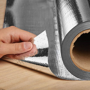
Pictured: 1 and 2. Heavy Duty Radiant Barrier, 3. Double Reflective Insulation, 4. Double Reflective Insulation with Staple Tab


